
Type P control
IEEE 1580 offshore control cable, 4 to 91 cores, XLPO, unarmoured, bronze braid armoured (B) or armoured and sheathed (BS), 0.6/1 kV
Type P control is the multi-core control cable of the Type P family: 0.6/1 kV to IEEE 1580, listed to UL 1309 as Type X110. 4 to 91 cores of 16 or 14 AWG (1.32 or 2.08 mm²) and 4 to 37 cores of 12 AWG (3.3 mm²). Up to and including 37 cores they are coloured, above that black with numbers. Unarmoured, B or BS. Supplied to order; the lead time is stated in the quote.
Type P control is a flexible multi-core offshore and marine cable to IEEE 1580, listed to UL 1309 / CSA 245 as Type X110, rated 0.6/1 kV with a conductor temperature of up to +110 °C. The conductors are soft annealed, tinned copper to IEEE 1580 Table 11, with 19 strands in 16, 14 and 12 AWG, insulated with cross-linked, flame-retardant polyolefin (XLPO). Up to and including 37 cores the cores are coloured to IEEE 1580 Table 22; above that they are black with printed numbers. The black, arctic-grade thermoset sheath resists oil, drilling mud, abrasion, chemicals and sunlight. The cable comes unarmoured, with a bronze basket-weave armour (B), and with that armour plus a thermoset outer sheath (BS). Type P control is flexible, easy to install and resistant to vibration. Only the BS version is suitable for Class I Division 1 and Zone 1. The power cable of the same family is Type P power.
Also known as: Type P control cable · IEEE 1580 cable · X110 cable
Applications
- Control, signalling and switching circuits on drilling rigs, drill ships and production platforms.
- Many control circuits in one cable, for example between a control panel and a machine.
- Installations designed to IEEE 45, or where the specification calls for Type P.
What to look out for
- Only the BS version is suitable for Class I Division 1 and Zone 1. NEC Article 337 requires fittings listed for the location there. State the version in your enquiry.
- The more cores, the lower the current per core: at +110 °C, 4 × 14 AWG may carry 27 A per core and 44 × 14 AWG only 10 A.
- The datasheet does not state that the sheath is halogen-free. If the specification calls for halogen-free to IEC 60754, choose a NEK 606 type such as RFOU.
- Type P falls outside EN 50575 and so has no CPR class. Where the cable is exposed to indoor air in a building, the Bbl does require a class; choose another cable there.
- Conductor
- Soft annealed, flexible stranded tinned copper acc. to IEEE 1580 Table 11; 19 strands in all three sizes.
- Insulation
- Cross-linked, flame-retardant polyolefin (XLPO), acc. to IEEE 1580 Type P and UL 1309 / CSA 245 Type X110.
- Core identification
- Colour code acc. to IEEE 1580 Table 22: coloured cores up to and including 37 conductors, black cores with printed numbers above 37.
- Sheath
- Black, arctic-grade, flame-retardant thermoset compound, resistant to oil, drilling mud, abrasion, chemicals and sunlight.
- Armour (B and BS)
- Basket-weave wire braid of bronze; tinned copper on request.
- Outer sheath (BS)
- Black, arctic-grade, flame-retardant thermoset compound over the armour, resistant to oil, drilling mud, abrasion, chemicals and sunlight. Sheath resistant to ester-based drilling mud acc. to NEK 606 on request.
- Rated voltage Uo/U
- 0.6/1 kV.
- Standard
- IEEE 1580 Type P; UL 1309 / CSA 245 Type X110; conductors acc. to IEEE 1580 Table 11.
- Max. conductor temperature
- +110 °C.
- Classification society ratings
- ABS +100 °C; DNV, Lloyd’s Register and Transport Canada +95 °C.
- Cold resistance
- Passes the CSA cold bend test (−40 °C) and cold impact test (−35 °C).
- Flame-retardant
- Acc. to IEC 60332-3 Category A and IEEE 1202.
- Hazardous areas
- Class I Division 1 and Zone 1 in the armoured and sheathed version (BS) only, terminated with fittings listed for the location (NEC Article 337).
- Approvals
- ABS, DNV, Lloyd’s Register, Transport Canada and United States Coast Guard; UL and CSA listed as marine shipboard cable.
- Reaction to fire (CPR)
- Outside the scope of EN 50575 (offshore and shipboard cable).
- Min. bending radius, unarmoured
- 6 × outer diameter (IEEE 45).
- Min. bending radius, armoured (B and BS)
- 8 × outer diameter (IEEE 45).
Three versions
| Version | Over the cores | Min. bending radius | Class I Div. 1 and Zone 1 |
|---|---|---|---|
| Unarmoured | Thermoset sheath | 6 × outer diameter | No |
| B, armoured | Sheath with the bronze braid as the outer layer | 8 × outer diameter | No |
| BS, armoured and sheathed | Sheath, bronze braid and outer sheath | 8 × outer diameter | Yes, with fittings listed for the location |
Dimensions and weight per version
| Unarmoured | B, armoured | BS, armoured and sheathed | |||||
|---|---|---|---|---|---|---|---|
| Cores × size | Equivalent c.s.a. (mm²) | Ø (mm) | kg/km | Ø (mm) | kg/km | Ø (mm) | kg/km |
| 4 × 16 AWG | 1.32 | 11.0 | 144 | 12.3 | 238 | 15.7 | 330 |
| 5 × 16 AWG | 1.32 | 11.9 | 174 | 13.2 | 277 | 16.3 | 375 |
| 7 × 16 AWG | 1.32 | 13.1 | 219 | 14.4 | 455 | 17.2 | 560 |
| 8 × 16 AWG | 1.32 | 14.8 | 301 | 16.0 | 430 | 19.4 | 554 |
| 10 × 16 AWG | 1.32 | 16.1 | 374 | 17.4 | 479 | 22.4 | 692 |
| 16 × 16 AWG | 1.32 | 18.3 | 496 | 19.6 | 656 | 24.4 | 923 |
| 20 × 16 AWG | 1.32 | 20.0 | 568 | 21.2 | 765 | 25.7 | 1,015 |
| 24 × 16 AWG | 1.32 | 22.9 | 817 | 24.1 | 961 | 29.3 | 1,339 |
| 37 × 16 AWG | 1.32 | 26.6 | 1,088 | 28.1 | 1,293 | 32.5 | 1,674 |
| 44 × 16 AWG | 1.32 | 29.8 | 1,409 | 31.1 | 1,686 | 35.6 | 1,752 |
| 60 × 16 AWG | 1.32 | 32.1 | 1,662 | 33.3 | 1,957 | 37.7 | 2,344 |
| 91 × 16 AWG | 1.32 | 39.4 | 2,399 | 40.6 | 2,792 | 46.5 | 3,426 |
| 4 × 14 AWG | 2.08 | 11.1 | 188 | 12.4 | 292 | 16.5 | 390 |
| 5 × 14 AWG | 2.08 | 12.2 | 228 | 13.4 | 341 | 17.5 | 455 |
| 6 × 14 AWG | 2.08 | 14.2 | 298 | 15.5 | 427 | 18.5 | 646 |
| 7 × 14 AWG | 2.08 | 14.0 | 332 | 15.3 | 440 | 18.7 | 616 |
| 10 × 14 AWG | 2.08 | 17.5 | 487 | 18.8 | 600 | 22.9 | 891 |
| 12 × 14 AWG | 2.08 | 18.1 | 530 | 19.4 | 668 | 24.4 | 948 |
| 14 × 14 AWG | 2.08 | 19.3 | 621 | 20.6 | 817 | 24.9 | 1,055 |
| 20 × 14 AWG | 2.08 | 23.7 | 890 | 25.0 | 1,054 | 29.5 | 1,426 |
| 24 × 14 AWG | 2.08 | 26.0 | 1,073 | 27.3 | 1,234 | 31.6 | 1,527 |
| 30 × 14 AWG | 2.08 | 27.3 | 1,159 | 28.6 | 1,421 | 33.3 | 1,755 |
| 37 × 14 AWG | 2.08 | 29.3 | 1,442 | 30.6 | 1,667 | 35.5 | 2,091 |
| 44 × 14 AWG | 2.08 | 32.3 | 1,621 | 33.6 | 1,924 | 38.1 | 2,235 |
| 91 × 14 AWG | 2.08 | 45.0 | 3,607 | 46.3 | 4,052 | 53.1 | 4,715 |
| 4 × 12 AWG | 3.3 | 13.1 | 299 | 14.4 | 368 | 17.0 | 475 |
| 5 × 12 AWG | 3.3 | 14.2 | 353 | 15.5 | 469 | 18.9 | 627 |
| 6 × 12 AWG | 3.3 | 15.5 | 420 | 16.8 | 591 | 20.7 | 731 |
| 10 × 12 AWG | 3.3 | 19.6 | 646 | 20.8 | 757 | 25.8 | 1,089 |
| 20 × 12 AWG | 3.3 | 25.9 | 1,198 | 27.2 | 1,402 | 32.0 | 1,777 |
| 24 × 12 AWG | 3.3 | 28.8 | 1,537 | 30.1 | 1,729 | 34.5 | 2,012 |
| 37 × 12 AWG | 3.3 | 32.8 | 1,890 | 34.1 | 2,204 | 39.4 | 2,692 |
Nominal manufacturer values, with a manufacturing tolerance of ±5%. The equivalent c.s.a. per size is the manufacturer’s value for its stranded conductor, not the nominal AWG cross-section (18 AWG: 19 strands of 0.0100 inch, 0.96 mm²; nominal 0.82 mm²). In a few sizes the diameters or weights on the sheet do not rise consistently with the size or the number of cores. We reproduce the values as published.
Conductor data per size
| Size | Equivalent c.s.a. (mm²) | Strands | R DC 25 °C (Ω/km) | R AC 110 °C (Ω/km) |
|---|---|---|---|---|
| 16 AWG | 1.32 | 19 | 15.1 | 20.1 |
| 14 AWG | 2.08 | 19 | 9.54 | 12.7 |
| 12 AWG | 3.3 | 19 | 5.99 | 7.95 |
AC resistance at 60 Hz.
16 AWG (1.32 mm²)
| Cores × size | +110 °C (A) | +100 °C (A) | +95 °C (A) |
|---|---|---|---|
| 4 × 16 AWG | 17 | 16 | 16 |
| 5 × 16 AWG | 14 | 13 | 13 |
| 7 × 16 AWG | 12 | 11 | 11 |
| 8 × 16 AWG | 12 | 11 | 11 |
| 10 × 16 AWG | 9 | 8 | 11 |
| 16 × 16 AWG | 9 | 8 | 11 |
| 20 × 16 AWG | 9 | 8 | 11 |
| 24 × 16 AWG | 8 | 7 | 11 |
| 37 × 16 AWG | 6 | 6 | 8 |
| 44 × 16 AWG | 6 | 6 | 8 |
| 60 × 16 AWG | 6 | 6 | 8 |
| 91 × 16 AWG | 6 | 6 | 8 |
14 AWG (2.08 mm²)
| Cores × size | +110 °C (A) | +100 °C (A) | +95 °C (A) |
|---|---|---|---|
| 4 × 14 AWG | 27 | 25 | 22 |
| 5 × 14 AWG | 21 | 20 | 18 |
| 6 × 14 AWG | 21 | 20 | 18 |
| 7 × 14 AWG | 19 | 18 | 15 |
| 10 × 14 AWG | 14 | 13 | 15 |
| 12 × 14 AWG | 14 | 13 | 15 |
| 14 × 14 AWG | 14 | 13 | 15 |
| 20 × 14 AWG | 14 | 13 | 15 |
| 24 × 14 AWG | 12 | 11 | 15 |
| 30 × 14 AWG | 12 | 11 | 13 |
| 37 × 14 AWG | 11 | 10 | 13 |
| 44 × 14 AWG | 10 | 9 | 11 |
| 91 × 14 AWG | 10 | 9 | 11 |
12 AWG (3.3 mm²)
| Cores × size | +110 °C (A) | +100 °C (A) | +95 °C (A) |
|---|---|---|---|
| 4 × 12 AWG | 33 | 31 | 27 |
| 5 × 12 AWG | 27 | 25 | 22 |
| 6 × 12 AWG | 27 | 25 | 22 |
| 10 × 12 AWG | 17 | 16 | 19 |
| 20 × 12 AWG | 17 | 16 | 19 |
| 24 × 12 AWG | 15 | 14 | 19 |
| 37 × 12 AWG | 13 | 12 | 16 |
Current ratings from the datasheet. At +110 °C and +100 °C to IEEE Std 45, at 45 °C ambient with a single layer of cables per hanger; for two layers multiply by 0.8. At +95 °C to Table 4/3C.10 of the 1997 ABS MODU rules, also at 45 °C. The classification society decides which column applies: ABS allows +100 °C; DNV, Lloyd’s Register and Transport Canada allow +95 °C. The four-core ratings assume that one conductor carries no normal current, such as an earthed neutral or an earth conductor. In free air the IEEE Std 45 values may be divided by 0.85.
Type P control or Type P instrumentation pairs?
Type P control
- single cores
- no screen
- switching and control circuits
Type P instrumentation pairs
- twisted pairs
- screen per pair and overall
- analogue measuring signals
Type P control has single cores without a screen, for switching and control circuits. Type P instrumentation pairs has twisted pairs, each with its own foil and drain wire, plus an overall screen, for analogue measuring signals that must not pick up interference. Choose control for switching and control circuits, and the pairs for measuring signals.
View Type P instrumentation pairs →Type P control or RFOU 0.6/1 kV?
Type P control
- IEEE 1580 and UL 1309
- XLPO, bronze braid (B, BS)
- sizes in AWG
RFOU 0.6/1 kV
- NEK TS 606
- EPR, tinned copper braid
- halogen-free, sizes in mm²
Both are 0.6/1 kV offshore cables that are also used for control circuits. Type P control follows IEEE 1580 and UL 1309, with XLPO insulation, sizes in AWG and, in the B and BS versions, a bronze braid. RFOU follows NEK TS 606, with EPR insulation, a tinned copper braid, a halogen-free sheath and sizes in mm². If the specification calls for IEEE 1580, choose Type P control; if it calls for NEK 606 or halogen-free, choose RFOU.
View RFOU 0.6/1 kV →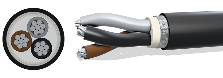
RFOU 0.6/1 kV
NEK 606 offshore power cable, halogen-free, braid armoured
Lead time: On request; the lead time is stated in the quote.
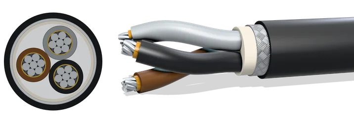
BFOU 0.6/1 kV
NEK 606 offshore fire-resistant power cable, halogen-free, braid armoured
Lead time: On request; the lead time is stated in the quote.
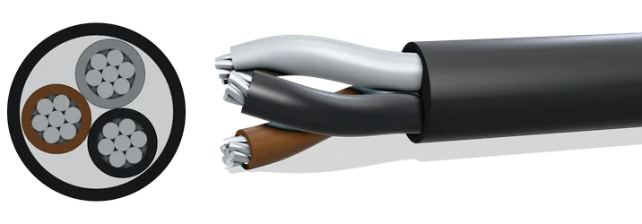
RU 0.6/1 kV
NEK 606 offshore power cable, halogen-free, unarmoured
Lead time: On request; the lead time is stated in the quote.
Not seeing what you need? Just ask. Our range goes well beyond this list. Ask us →